Polar Eyes
Color Selection In
Birefringent Materials
Hank Black, Samson Black
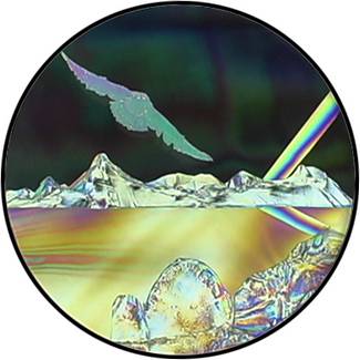
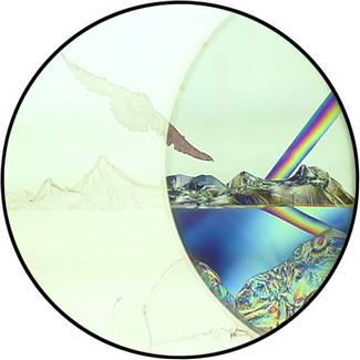
We have created a metaphor of hidden potential. The colorless plastic reveals a spectrum of light…the frozen wilderness reveals a spectrum of life. It goes through its seemingly magical transformations by exploiting the properties of clear, birefringent plastics viewed through linear polarizers. Please note that no digital or video manipulations were used in creating the colors or transformations. The artwork is made of transparent plastics with carefully selected chemical composition, thickness, and angular orientation. All that is needed to make it come alive with the effects you see is a source of white light and properly oriented polarizing filters.
A simple explanation of the technical details is in order. An understanding of linear polarization and birefringent materials enhances the appreciation of this piece. Our video, Polar Eyes, touches on these technical matters as well. This printed version primarily reinforces the video explanation by affording the interested reader another way to study the material at his own pace. Many of the topics are purposely repeated.
To begin, let us define some basic terms. Polarized light consists of waves of electric and magnetic fields whose vibrations are restricted to a specific orientation.1 For the rest of this paper, please understand that the term “polarized” means linearly polarized. Normal unpolarized light contains waves of every orientation in statistically equal proportions. This is illustrated by the views on the top row of the chart on page 2: Polarization of Light Waves. The other three rows show linearly polarized light, having passed through filters of varying orientations.
Polarization of Light Waves
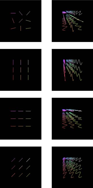

The linear polarizing filter transmits only the components of those waves oscillating in the direction of its axis. Normally, a piece of polarizing film appears gray, as it transmits slightly less than half of the unpolarized light incident upon it. When crossed with another filter, it appears black. Our piece employs filters that transmit 38% of visible light. This is similar to material found on certain sunglasses, camera filters, and LCD displays on hand calculators, etc. These applications do not normally reveal the colors we display in our polarized art. For this, a second filter, known as an analyzer, is necessary.
The filters themselves have a directional grain on the molecular scale. So, when light passes through two filters whose axes are aligned, the light is hardly affected.
The picture on the left depicts light passing through a polarizer and then an analyzer, aligned in parallel. The light is coming from the top, left corner in this series of images.
Here, the analyzer is oriented at 90º, or crossed position, and the light is extinguished.
All in between angles cause partial reduction or darkening of the light transmitted.2 Note: the polarization of the light exiting the analyzer is twisted to match its orientation.
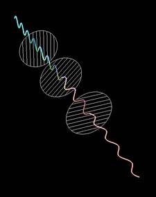
This is an image of what happens when a third polarizer is interposed between two crossed filters. Contrary to common sense, blocked light can be resurrected. This effect is not limited to three filters.
In the case of three filters, this phenomenon is maximized when the intermediate filter is set at 45º. However, when this filter is set at either 0º or 90º, the light is once again extinguished. As long as no two consecutive filters are crossed, some light survives.3
This counterintuitive effect highlights the unusual nature of polarizing filters.
By interposing certain clear, colorless substances rather than a third polarizer, interesting as well as beautiful effects can be produced. Light can also be resurrected. Now, however, strong colors can be seen as well.
This effect is what our entry is all about. The multitude of colors can be created and extinguished as well as controlled and changed. The many parameters that we have to work with offer a very versatile and exciting artistic medium. We control the viewing angle and the orientation of the various layers, as well as the thickness and chemistry of the optically active substances.
In our artwork, special plastics are situated between crossed polarizers to produce vibrant colors. These materials are selected for their birefringence, the technical term for a fascinating optical property. On a microscopic scale, the configuration of molecules in these materials is anisotropic, meaning that the crystalline lattice has a distinguishable orientation. We can induce this condition locally in an isotropic material by applying stress. Either way, the effect of this birefringence on the transmission of light is twofold. First of all, light is decomposed into two beams, each of which is polarized parallel to one of the axes of the material. Secondly, the two components of the light propagate at different speeds. Neither of these effects is color-specific; however, a combination of both of these effects in concert with polarizing filters yields the beautiful spectrum of colors we observe.
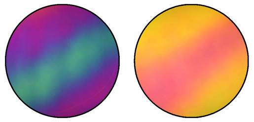
Here we have two views of a single piece of birefringent material, transmitting light of different polarizations.
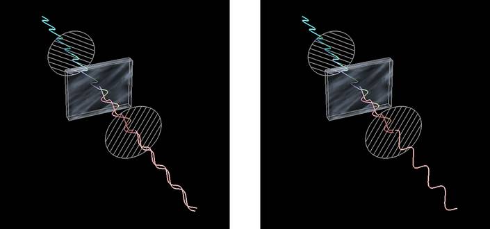
Consider the configuration of a birefringent sandwiched between two polarizing filters, illustrated above. Here we trace a single wave of light through the layers. After passing through the first filter, ordinary white light is linearly polarized. Within the birefringent, the light is split into two parts, with one wave traveling faster than the other. As a result, one wave leads the other by a fixed distance when they exit the material. This displacement between the components does not depend on the wavelength of the light. Since the two beams of light are polarized at right angles, they have no effect on each other. Upon encountering the analyzer, the two components are twisted into the same polar orientation. Now they can recombine. The superposition principle comes into play, as the waves interfere. The right hand diagram, above, shows the resultant wave sum. Let’s examine the specifics of this interference, particularly with regard to color.

Recall that one component wave has moved ahead of the other a fixed distance. The size of this displacement is fully determined by the nature of the birefringent layer, regardless of the color of the light passing through. The diagram on the left shows this displacement as the distance between the two vertical gray lines. But, since this displacement represents a different fraction of the wavelength for each color, the phase difference is color dependent. For example, this displacement causes a small relative shift at the red end of the visible spectrum, where the wavelengths are longer. For the shorter wavelengths, the same displacement is equivalent to a greater relative phase shift. The result is that some wavelengths interfere constructively, while others interfere destructively. The thickness of the birefringent and its specific molecular geometry determine the predominant color.
The apparent color of the light emerging from the birefringent-polarizer configuration is illustrated graphically by the Michel-Levy chart. Bear in mind, these are the colors that predominate, as other component colors of the white light exist but are attenuated by destructive interference.4
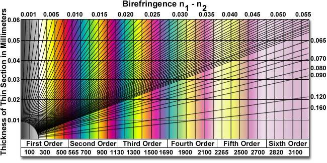
Michel-Levy Chart
On the above chart, the diagonal lines represent different optically active materials. For example, the radial line with the shallowest slope is the most birefringent material shown here. Very slight changes in thickness alter the color drastically. These are the materials we use to produce the more brilliant hues in our artwork.

Here we have two views of a single array of birefringent material, transmitting light of different polarizations. The different thicknesses of each stripe determine the colors produced.
For the current project, I incorporated subtle new technical twists. Certain materials, such as polypropylene, are profoundly anisotropic in their manufactured form and are therefore highly birefringent. Other plastics only display birefringence when put under physical stress. This property can be reversible when the stress is slight or permanent when the stress is greater. Thermoforming, or changing shapes with heat, sets permanent color patterns that can be analyzed with our filters as well.
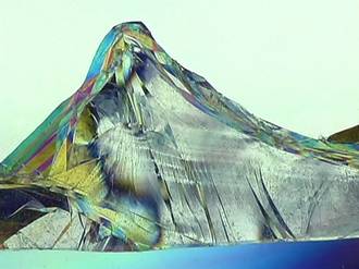
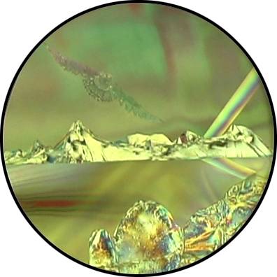
The mountains in Polar Eyes were formed by stretching a fine isotropic film to just the right tension and capturing the shape with an original sculpting method. The resulting mountains have an average thickness of less than one hundredth of an inch.

The rainbow was made from a type of polycarbonate plastic. These sheets have a specific stress of formation pattern.

The Aurora Borealis was made with a polyester material of borderline birefringence. It was carefully bent to present varying thickness and therefore varying color to the viewer.

The foreground ice blocks were made by thermoforming PETG5, a heavier plastic of relatively low birefringence.
The overall dimensions of Polar Eyes measure 24 inches x 24 inches x 10 inches deep, including the light box. The active area is a 19 inch diameter circle by 3 inches deep. The clear plastic artwork is sandwiched between two polarizing filters that can be rotated by hand for maximum control and interactive discovery. It is adaptable to a motor drive for display purposes.
White light is our only source of illumination. Yet, the originally clear plastic seems to glow with changing colors. The scene appears as winter or summer, night or day, static or changing. At certain times the Aurora Borealis appears and scintillates.
8722 Diceman Drive
Dallas, Texas 75218 U.S.A.
Tel: 214 535 9597
hank@hankblackart.com
1 Further mention of the magnetic component of light is suppressed for clarity, here and in the video.
2Malus’ Law: It = Ii·cos²(θ). For example, if the polarizers are at 30º, then 75% of the incident light is transmitted.
3 When interposing more polarizing filters between two crossed filters, maximum transmission occurs when the angles between consecutive are polarizers equal. For example, two intermediates set at 30º and 60º maximize transmission.
4 The extinguished colors are not converted to heat by absorption, as in coloration by pigment. Destructive interference is solely responsible.
5 Polyethylene Terepthalate Glycol